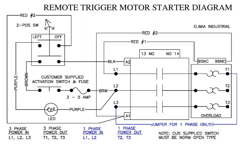
Below is a generic wiring diagram for an IEC motor starter.
With this design the voltage to power the contactor is "taken" from two legs of the supply power, L1 and L2. This means that this set up will have a coil voltage same as supply Voltage. This diagram can be used for 230V 3 phase, 230V 1 phase and 480V 3 phase. Elimia calls this a ACMS type.
How it works. Starting from L1 which will be one leg of your power supply. Red #1 runs to connection 95 on the overload. 95 and 96 are the normally closed contact of the overload. If your starter trips this N/C contact will open causing the starter to disengage. From 96 Red #2 travels to coil connection A1. If A1 does not have power the contactor will not engage.
L2, which is the second leg of your power supply and the starting point of brown and purple. We will focus on the brown wire first. On this starter set up commonly used for air compressors, the starter is set up to engage from a customer supplied switch. On an air compressor that would be the pressure range switch. It is always good practice to re-fuse wiring if it is resized and leaves the enclosure. In this case we are recommending a fuse be installed if the wiring is not sized properly for the supply power. If the wiring leaving the enclosure is sized properly for circuit then fusing would not be required. So, we have supply wire Brown connected to L2 - extended and run to a limit switch. On the other side of the customer supplied switch is a second wire Brown to complete the circuit. As supplied by Elimia there are two Brown wires loose in the complete assembly that will be extended. Both wires are brown as it doesn't matter about polarity in the limit switch application. Once the circuit is completed by closing the limit switch power pass to the "enable" switch installed on the enclosure cover. This switch is a 2 postion with N/O contacts. If the maintained rotary switch is in the off or open position the starter will not engage. Once the enable switch is turned on the contacts close. The Black wire then gets power and completes the circuit at connection A2. So, for this starter to engage a both the customer supplied limit switch and the Elimia rotary switch must be closed.
Additionally in this wiring diagram there is an indicator light. This light is wired to show when the starter is enabled. So when the rotary switch in ON, power is passing through the switch from Red #2 through the contact and feeds purple to power the light. This light will remain ON even if the customer supplied switch is open to serve as a reminder that the machine is subject to start.
On more thing, on this generic diagram there are special connections and a jumper shown in blue. In order to use a 3 phase starter on single phase 230V a jumper must be installed. Since the overload is "looking" for power passing through all 3 load connections T1, T2 and T3 the jumper must be installed for accurate trips. So note the line side connections in this configuration, power is applied to L1 and L2. Now note the load side connections, T2 and T3. The jumper shown in blue is basically just running one leg of the single phase through the starter two times!